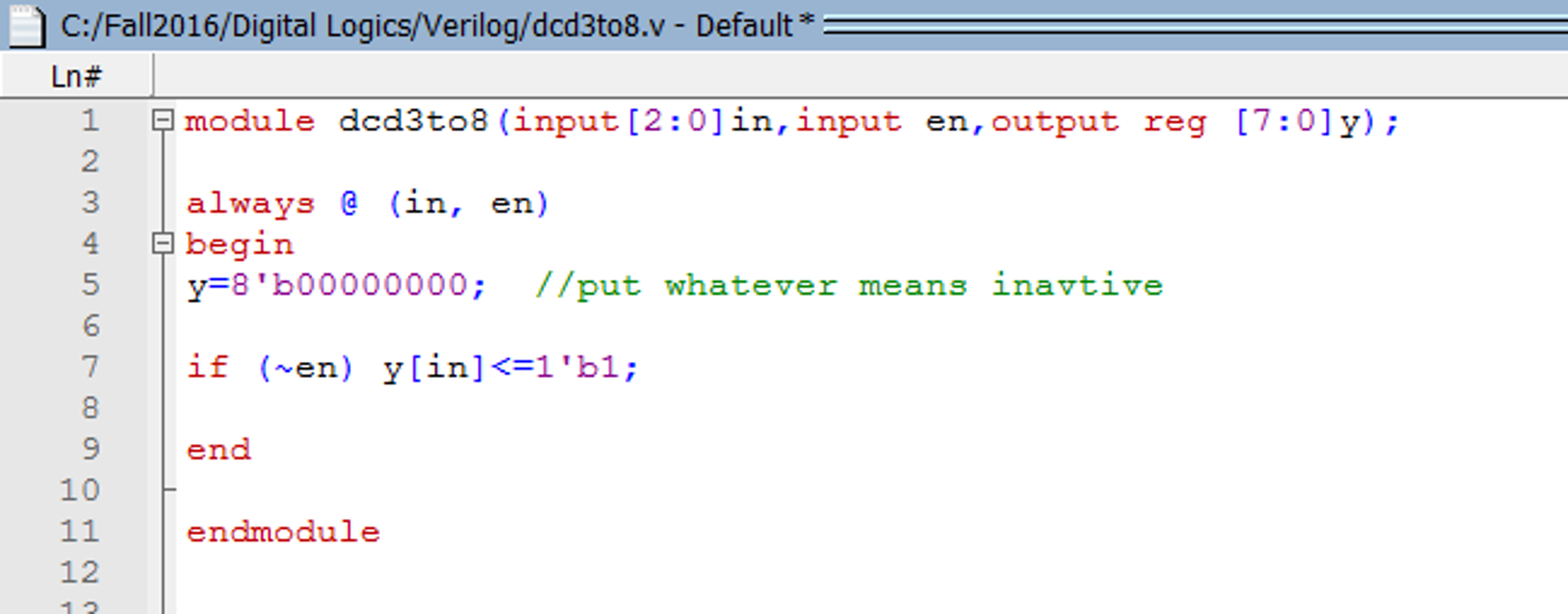
Decoder is a digital circuit that can select a line according to the input pattern. Decoder can be used as a control unit for a MCU,processor etc. 4 to 16 line decoder verilog code arr given bellow Design a 4 to 16 decoder using Verilog HDL. The inputs are a four-bit vector W= w1 w2 w3 w4 and an enable signal En. Designing of 2 to 4 Line Decoder Circuit. Similar to the multiplexer circuit, the decoder is not restricted to a particular address line, and thus can have more than two outputs (with two, three, or four address lines). The decoder circuit can decode a 2, 3, or 4-bit binary number, or can decode up to 4, 8, or 16 time-multiplexed signals.

4 To 16 Decoder Using 2 To 4 Decoder Verilog Code
//Main Module
module decrd_2_to_4(
input [0:1] X,
output [0:3] Y
);
wire w1,w2;
not A0(w1,X[0]);
not A1(w2,X[1]);
and AN0(w1,w2,Y[0]);
and AN1(w1,X[1],Y[1]);
and AN2(X[0],w2,Y[2]);
and AN3(X[0],X[1],Y[3]);
endmodule
//Test Module
module test_decrd_2_to_4;
// Inputs
reg [0:1] X;
// Outputs
wire [0:3] Y;
// Instantiate the Unit Under Test (UUT)
decrd_2_to_4 uut (
.X(X),
.Y(Y)
);
initial begin
// Initialize Inputs
X = 0;
// Wait 100 ns for global reset to finish
#100;
// Add stimulus here
#50 X[0]=0;
X[1]=1;
#50 X[0]=1;
X[1]=0;
#50 X[0]=1;
X[1]=1;
end
initial begin
$display(' x0 x1 B0 B1 B2 B3n');
$monitor(' %d %d %d %d %d
%dn',X[0],X[1],Y[0],Y[1],Y[2],Y[3]);
end
endmodule